Time-of-flight camera
A time-of-flight camera (ToF camera) is a range imaging camera system that resolves distance based on the known speed of light, measuring the time-of-flight of a light signal between the camera and the subject for each point of the image. The time-of-flight camera is a class of scannerless LIDAR, in which the entire scene is captured with each laser or light pulse, as opposed to point-by-point with a laser beam such as in scanning LIDAR systems.[1]
Time-of-flight camera products for civil applications began to emerge around 2000,[2] as the semiconductor processes became fast enough for such devices. The systems cover ranges of a few meters up to about several kilometers depending upon the detector material being used.
The imager module is made from (1) CMOS detectors which capture light pulses in the visible range, (2) PIN diodes or (3) avalanche photo diodes (APDs). Each material has inherent strengths and is chosen based upon application requirements.
The distance resolution ranges from sub-centimeter to several centimeters depending upon the range. The lateral resolution of time-of-flight cameras is generally low compared to standard 2D video cameras, with most commercially available devices at 320 × 240 pixels or less as of 2011.[3][4][5][6][7] Compared to 3D laser scanning methods for capturing 3D images, TOF cameras operate very quickly, providing up to 100 images per second.[8]
Contents |
Types of devices
Several different technologies for time-of-flight cameras have been developed.
Pulsed light source with digital time counters
There are devices with a pulsed laser and a custom imaging integrated circuit with a fast counter behind every pixel. These devices produce depth values for each pixel on every frame. Typical image sizes are 128 x 128 pixels. Ranges up to 22,000 feet with an eye-safe narrow beam have been achieved. Detectors are typically InGaAs (indium-gallium-arsenide) devices.[9]
RF-modulated light sources with phase detectors
Photonic Mixer Devices (PMD),[10] the Swiss Ranger, and CanestaVision[11] work by modulating the outgoing beam with an RF carrier, then measuring the phase shift of that carrier on the receive side. This approach has a modular error challenge; ranges are mod the maximum range, which is the RF carrier wavelength. The Swiss Ranger is a compact, short-range device, with ranges of 5 or 10 meters, with 176 x 144 pixels. With phase unwrapping algorithms, the maximum uniqueness range can be increased. The PMD can provide ranges up to 60m. Illumination is pulsed LEDs, rather than a laser.[12] CanestaVision developer Canesta was purchased by Microsoft in 2010.
Range gated imagers
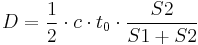
These devices have a built-in shutter in front of the image sensor that opens and closes at the same rate as the light pulses are sent out. Because part of every returning pulse is blocked by the shutter according to its time of arrival, the amount of light received relates to the distance the pulse has traveled. The distance can be calculated using the equation, z = R (S2 − S1) / 2(S1 + S2) + R / 2 for an ideal camera. R is the camera range, determined by the round trip of the light pulse, S1 the amount of the light pulse that is received, and S2 the amount of the light pulse that is blocked.[13][14]
The ZCam by 3DV Systems[1] is a range-gated system. Microsoft purchased 3DV in 2009.
Similar principles are used in the ToF camera line developed by the Fraunhofer Institute of Microelectronic Circuits and Systems and TriDiCam. These cameras employ photodetectors with a fast electronic shutter.
Range gated imagers can also be used in 2D imaging to suppress anything outside a specified distance range, such as to see through fog. A pulsed laser provides illumination, and an optical gate allows light to reach the imager only during the desired time period.[15][16]
Components
A time-of-flight camera consists of the following components:
- Illumination unit: It illuminates the scene. As the light has to be modulated with high speeds up to 100 MHz, only LEDs or laser diodes are feasible. The illumination normally uses infrared light to make the illumination unobtrusive.
- Optics: A lens gathers the reflected light and images the environment onto the image sensor. An optical band pass filter only passes the light with the same wavelength as the illumination unit. This helps suppress background light.
- Image sensor: This is the heart of the TOF camera. Each pixel measures the time the light has taken to travel from the illumination unit to the object and back. Several different approaches are used for timing; see types of devices above.
- Driver electronics: Both the illumination unit and the image sensor have to be controlled by high speed signals. These signals have to be very accurate to obtain a high resolution. For example, if the signals between the illumination unit and the sensor shift by only 10 picoseconds, the distance changes by 1.5 mm. For comparison: current CPUs reach frequencies of up to 3 GHz, corresponding to clock cycles of about 300 ps - the corresponding 'resolution' is only 45 mm.
- Computation/Interface: The distance is calculated directly in the camera. To obtain good performance, some calibration data is also used. The camera then provides a distance image over a USB or Ethernet interface.
Principle
The simplest version of a time-of-flight camera uses light pulses. The illumination is switched on for a very short time, the resulting light pulse illuminates the scene and is reflected by the objects. The camera lens gathers the reflected light and images it onto the sensor plane. Depending on the distance, the incoming light experiences a delay. As light has a speed of approximately c = 300,000,000 meters per second, this delay is very short: an object 2.5 m away will delay the light by:

The pulse width of the illumination determines the maximum range the camera can handle. With a pulse width of e.g. 50 ns, the range is limited to

These short times show that the illumination unit is a critical part of the system. Only with some special LEDs or lasers is it possible to generate such short pulses.
The single pixel consists of a photo sensitive element (e.g. a photo diode). It converts the incoming light into a current. In analog timing imagers, connected to the photo diode are fast switches, which direct the current to one of two (or several) memory elements (e.g. a capacitor) that act as summation elements. In digital timing imagers, a time counter, running at several gigahertz, is connected to each photodetector pixel and stops counting when light is sensed.
In the diagram of an analog timer, the pixel uses two switches (G1 and G2) and two memory elements (S1 and S2). The switches are controlled by a pulse with the same length as the light pulse, where the control signal of switch G2 is delayed by exactly the pulse width. Depending on the delay, only part of the light pulse is sampled through G1 in S1, the other part is stored in S2. Depending on the distance, the ratio between S1 and S2 changes as depicted in the drawing.[11] Because only small amounts of light hit the sensor within 50 ns, not only one but several thousands pulses are sent out (repetition rate tR) and gathered, thus increasing the signal to noise ratio.
After the exposure, the pixel is read out and the following stages measure the signals S1 and S2. As the length of the light pulse is defined, the distance can be calculated with the formula:
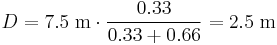
In the example, the signals have the following values: S1 = 0.66 and S2 = 0.33. The distance is therefore:
In the presence of background light, the memory elements receive an additional part of the signal. This would disturb the distance measurement. To eliminate the background part of the signal, the whole measurement can be performed a second time with the illumination switched off. If the objects are further away than the distance range, the result is also wrong. Here, a second measurement with the control signals delayed by an additional pulse width helps to suppress such objects. Other systems work with a sinusoidally modulated light source instead of the pulse source.
Advantages
Simplicity
In contrast to stereo vision or triangulation systems, the whole system is very compact: the illumination is placed just next to the lens, whereas the other systems need a certain minimum base line. In contrast to laser scanning systems, no mechanical moving parts are needed.
Efficient distance algorithm
It is very easy to extract the distance information out of the output signals of the TOF sensor, therefore this task uses only a small amount of processing power, again in contrast to stereo vision, where complex correlation algorithms have to be implemented. After the distance data has been extracted, object detection, for example, is also easy to carry out because the algorithms are not disturbed by patterns on the object.
Speed
Time-of-flight cameras are able to measure the distances within a complete scene with one shot. As the cameras reach up to 100 frames per second, they are ideally suited to be used in real-time applications.
Disadvantages
Background light
Although most of the background light coming from artificial lighting or the sun is suppressed, the pixel still has to provide a high dynamic range. The background light also generates electrons, which have to be stored. For example, the illumination units in today's TOF cameras can provide an illumination level of about 1 watt. The Sun has an illumination power of about 50 watts per square meter after the optical bandpass filter. Therefore, if the illuminated scene has a size of 1 square meter, the light from the sun is 50 times stronger than the modulated signal.
Interference
If several time-of-flight cameras are running at the same time, the cameras may disturb each others' measurements. There exist several possibilities for dealing with this problem:
- Time multiplexing: A control system starts the measurement of the individual cameras consecutively, so that only one illumination unit is active at a time.
- Different modulation frequencies: If the cameras modulate their light with different modulation frequencies, their light is collected in the other systems only as background illumination but does not disturb the distance measurement.
Multiple reflections
In contrast to laser scanning systems, where only a single point is illuminated at once, the time-of-flight cameras illuminate a whole scene. Due to multiple reflections, the light may reach the objects along several paths and therefore, the measured distance may be greater than the true distance.
Applications
Automotive applications
Time-of-flight cameras are also used in assistance and safety functions for advanced automotive applications such as active pedestrian safety, precrash detection and indoor applications like out-of-position (OOP) detection.[18][19][20]
Human-machine interfaces and gaming
As time-of-flight cameras provide distance images in real time, it is easy to track movements of humans. This allows new interactions with consumer devices such as televisions. Another topic is to use this type of cameras to interact with games on video game consoles.[21]
Measurement and machine vision
Other applications are measurement tasks, e.g. for the fill height in silos. In industrial machine vision, the time-of-flight camera helps to classify objects and help robots find the items, for instance on a conveyor. Door controls can distinguish easily between animals and humans reaching the door.
Robotics
Another use of these cameras is the field of robotics: Mobile robots can build up a map of their surroundings very quickly, enabling them to avoid obstacles or follow a leading person. As the distance calculation is simple, only little computational power is used.
Brands
- Active brands (as of 2011)
- D-IMager - TOF camera by Panasonic Electric Works[22]
- DepthSense - TOF cameras and modules, including RGB sensor and microphones by SoftKinetic[23]
- Fotonic - TOF cameras and software powered by Canesta CMOS chip[24]
- PMD[vision] - TOF imager, modules, cameras and software by PMDTechnologies[25]
- SwissRanger - an industrial TOF-only camera line originally by the Centre Suisse d'Electronique et Microtechnique, S.A. (CSEM), now developed by the spin out company Mesa Imaging[26]
- 3D MLI Sensor - TOF imager, modules, cameras, and software by IEE (International Electronics & Engineering), based on modulated light intensity (MLI)[27]
- 2+3D - High-resolution SXGA (1280×1024) TOF camera in development by startup company odos imaging, integrating conventional image capture with TOF ranging in the same sensor. Based on technology developed at Siemens.[28]
- TOFCam Stanley - TOF camera by Stanley Electric[29]
- TriDiCam - TOF modules and software, the TOF imager originally developed by Fraunhofer Institute of Microelectronic Circuits and Systems, now developed by the spin out company TriDiCam[30]
- Defunct brands
- CanestaVision - TOF modules and software by Canesta (company acquired by Microsoft in 2010)
- OptriCam - TOF cameras and modules by Optrima (rebranded DepthSense prior to SoftKinetic merger in 2011)
- ZCam - TOF camera products by 3DV Systems, integrating full-color video with depth information (assets sold to Microsoft in 2009)
See also
References
- ^ a b Iddan, Gavriel J.; Yahav, Giora (2001-01-24). "3D imaging in the studio (and elsewhere…)". Proceedings of SPIE (San Jose, CA: SPIE) 4298: pp. 48. 2003-04-29. doi:10.1117/12.424913. Archived from the original on 2009-06-12. http://web.archive.org/web/20090612071500/http://www.3dvsystems.com/technology/3D%20Imaging%20in%20the%20studio.pdf. Retrieved 2009-08-17. "The [time-of-flight] camera belongs to a broader group of sensors known as scanner-less LIDAR (i.e. laser radar having no mechanical scanner); an early [1990] example is [Marion W.] Scott and his followers at Sandia."
- ^ "Product Evolution". 3DV Systems. Archived from the original on 2009-02-28. http://web.archive.org/web/20090228203547/http://www.3dvsystems.com/technology/product.html#1. Retrieved 2009-02-19. "Z-Cam, the first depth video camera, was released in 2000 and was targeted primarily at broadcasting organizations."
- ^ Schuon, Sebastian; Theobalt, Christian; Davis, James; Thrun, Sebastian (2008-07-15). "High-quality scanning using time-of-flight depth superresolution". written at Anchorage, Alaska. IEEE Computer Society Conference on Computer Vision and Pattern Recognition Workshops, 2008. Institute of Electrical and Electronics Engineers. pp. 1–7. doi:10.1109/CVPRW.2008.4563171. ISBN 978-1-4244-2339-2. http://www-cs.stanford.edu/people/theobalt/TOF_CV_Superresolution_final.pdf. Retrieved 2009-07-31. "The Z-cam can measure full frame depth at video rate and at a resolution of 320×240 pixels."
- ^ "Canesta's latest 3D Sensor - "Cobra" ... highest res CMOS 3D depth sensor in the world" (Flash Video). Sunnyvale, California: Canesta. 2010-10-25. http://www.youtube.com/watch?v=5_PVx1NbUZQ. "Canesta "Cobra" 320 x 200 Depth Sensor, capable of 1mm depth resolution, USB powered, 30 to 100 fps […] The complete camera module is about the size of a silver dollar"
- ^ PMD[vision] CamCube 2.0 Datasheet (No. 20090601 ed.). Siegen, Germany: PMDTechnologies. 2009-06-01. p. 5. http://www.pmdtec.com/fileadmin/pmdtec/downloads/documentation/datasheet_camcube.pdf. Retrieved 2009-07-31. "Type of Sensor: PhotonICs PMD 41k-S (204 x 204)"
- ^ SR4000 Data Sheet (Rev 2.6 ed.). Zürich, Switzerland: Mesa Imaging. August 2009. p. 1. http://www.mesa-imaging.ch/dlm.php?fname=pdf/SR4000_Data_Sheet.pdf. Retrieved 2009-08-18. "176 x 144 pixel array (QCIF)"
- ^ PMD[vision] S3 Datasheet (No. 20090601 ed.). Siegen, Germany: PMDTechnologies. 2009-06-01. p. 4. http://www.pmdtec.com/fileadmin/pmdtec/downloads/documentation/datasheet_s3.pdf. Retrieved 2009-07-31. "Type of sensor—PhotonICs 3k-S2, resolution: 64[V] x 48[H] pixels"
- ^ "2+3D - real world in real time". odos imaging. http://www.odos-imaging.com/view.php/page/index. Retrieved 2011-10-20. "With capability of up to 100 frames per second, very fast moving objects can be captured."
- ^ Stettner, Roger and Bailey, Howard. Eye-safe laser radar 3D imaging. Advanced Scientific Concepts. http://www.advancedscientificconcepts.com/technology/documents/Eye-safepaper.pdf.
- ^ Christoph Heckenkamp: Das magische Auge - Grundlagen der Bildverarbeitung: Das PMD Prinzip. In: Inspect. Nr. 1, 2008, S. 25–28.
- ^ a b Gokturk, Salih Burak; Yalcin, Hakan; Bamji, Cyrus (2005-01-24). "A Time-Of-Flight Depth Sensor - System Description, Issues and Solutions". IEEE Computer Society Conference on Computer Vision and Pattern Recognition Workshops, 2004. Institute of Electrical and Electronics Engineers. pp. 35–45. doi:10.1109/CVPR.2004.291. Archived from the original on 2007-06-23. http://www.canesta.com/assets/pdf/technicalpapers/CVPR_Submission_TOF.pdf. Retrieved 2009-07-31. "The differential structure accumulates photo-generated charges in two collection nodes using two modulated gates. The gate modulation signals are synchronized with the light source, and hence depending on the phase of incoming light, one node collects more charges than the other. At the end of integration, the voltage difference between the two nodes is read out as a measure of the phase of the reflected light."
- ^ "Mesa Imaging - Products". August 17, 2009. http://www.mesa-imaging.ch.
- ^ Medina A, Gayá F, and Pozo F. Compact laser radar and three-dimensional camera. 23 (2006). J. Opt. Soc. Am. A. pp. 800–805. http://www.opticsinfobase.org/abstract.cfm?URI=josaa-23–4–800.
- ^ Medina, Antonio. Three Dimensional Camera and Rangefinder. January 1992. United States Patent 5081530.
- ^ http://www.laseroptronix.se/gated/sealynx.pdf
- ^ "Sea-Lynx Gated Camera - active laser camera system". http://www.laseroptronix.se/gated/sealynx.pdf.
- ^ "CCD/CMOS Lock-In Pixel for Range Imaging: Challenges, Limitations and State-of-the-Art" - CSEM
- ^ Hsu, Stephen; Acharya, Sunil; Rafii, Abbas; New, Richard (2006-04-25). "Performance of a Time-of-Flight Range Camera for Intelligent Vehicle Safety Applications". Advanced Microsystems for Automotive Applications 2006. Springer. pp. 205–219. doi:10.1007/3-540-33410-6_16. ISBN 978-3-540-33410-1. Archived from the original on 2006-12-06. http://www.canesta.com/assets/pdf/technicalpapers/canesta_amaa06_paper_final1.pdf. Retrieved 2009-09-36.
- ^ "PMDTec's 3D ToF technology for AUDI: Tomorrow’s driver assistance and safety systems" (Press release). PMDTechnologies. 2011-11-21. http://www.pmdtec.com/news-press/news/detail/pmdtecs-3d-tof-technology-for-audi-tomorrows-driver-assistance-and-safety-systems/.
- ^ Elkhalili, Omar; Schrey, Olaf M.; Ulfig, Wiebke; Brockherde, Werner; Hosticka, Bedrich J. (September 2006), "A 64x8 pixel 3-D CMOS time-of flight image sensor for car safety applications", European Solid State Circuits Conference 2006, pp. 568–571, doi:10.1109/ESSCIR.2006.307488, ISBN 978-1-4244-0302-8, http://publica.fraunhofer.de/documents/N-48683.html, retrieved 2010-03-05
- ^ Captain, Sean (2008-05-01). "Out of Control Gaming". PopSci.com. Popular Science. http://www.popsci.com/gear-gadgets/article/2008-05/out-control-gaming. Retrieved 2009-06-15.
- ^ http://pewa.panasonic.com/components/built-in-sensors/3d-image-sensors/d-imager/
- ^ http://www.softkinetic.com/Solutions/DepthSensecameras.aspx
- ^ http://www.fotonic.com/content/Products/Default.aspx
- ^ http://www.pmdtec.com/
- ^ http://www.mesa-imaging.ch/prodview4k.php
- ^ http://www.iee.lu/technologies
- ^ http://www.odos-imaging.com
- ^ http://www.brainvision.co.jp/xoops/modules/tinyd4/index.php?id=5
- ^ http://www.tridicam.net/en/products/array-sensor
External links
- ARTTS - Research project on time-of-flight cameras funded by the European Commission (under Information Society Technologies)
- Workshop on Time of Flight based Computer Vision (TOF-CV) at the 2008 IEEE Conference on Computer Vision and Pattern Recognition
- Gesturespace - a user interface design project based on time-of-flight cameras at the Zurich University of the Arts (ZHdK)
- "Calibration and Registration for Precise Surface Reconstruction with TOF Cameras" - Institute of Robotics and Mechatronics, German Aerospace Center
- "First steps in enhancing 3D vision technique using 2D/3D sensors" - Center for Sensor Systems, University of Siegen
- "Technological overview of Time-of-Flight cameras" - Description of the technology and comparision to other real-time 3-D acquisition techniques, Metrilus GmbH